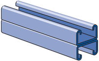

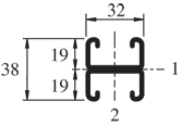
| Elements of Section - A3301 | ||
| Area of Section |
0.459 in2 (3.0 cm2)
|
|
|
Axis 1-1
|
Axis 2-2
|
|
| Moment of Inertia (I) |
0.077 in4 (3.2 cm4)
|
0.104 in4 (4.3 cm4)
|
| Section Modulus (S) |
0.103 in3 (1.7 cm3)
|
0.167 in3 (2.7 cm3)
|
| Radius of Gyration (r) |
0.411 in (1.0 cm )
|
0.477 in (1.2 cm )
|
|
||||||||||||||||||||||||||||||||||||||||||||||||||||||||||||||||||||||||||||
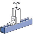
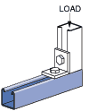
| Beam Loading - A3301 | ||||||
| Span (in) |
Max Allowable Uniform Load (lbs) |
Defl at Uniform load (in) |
Uniform Loading at Deflection |
Lateral Bracing Reduction Factor |
||
| Span /180 (lbs) |
Span /240 (lbs) |
Span /360 (lbs) |
||||
| 18 | *990 | 0.03 | *990 | *990 | *990 | 1.00 |
| 24 | 860 | 0.07 | 860 | 860 | 850 | 1.00 |
| 36 | 580 | 0.15 | 580 | 560 | 380 | 1.00 |
| 48 | 430 | 0.27 | 420 | 320 | 210 | 0.99 |
| 60 | 350 | 0.43 | 270 | 200 | 140 | 0.95 |
| 72 | 290 | 0.62 | 190 | 140 | 90 | 0.91 |
| 84 | 250 | 0.85 | 140 | 100 | 70 | 0.88 |
| 96 | 220 | 1.11 | 110 | 80 | 50 | 0.84 |
|
*Load limited by weld shear
|
||||||
Notes:
- Above loads include the weight of the member. This weight must be deducted to arrive at the net allowable load the beam will support.
- Long span beams should be supported so as to prevent rotation and twist.
- Allowable uniformly distributed loads are listed for various simple spans, that is, a beam on two supports. If load is concentrated at the center of the span, multiply load from the table by 0.5 and corresponding deflection by 0.8.
- The lateral bracing factor should be multiplied by the load to determine the load retained based on the distance between lateral braces.
| Part No. | Finish | Length | Weight | Box Qty. |
|
A3301
|
16
|
156.00
|
400
|
|
|
A3301
|
16
|
156.00
|
400
|
|
|
A3301
|
16
|
156.00
|
400
|