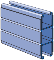
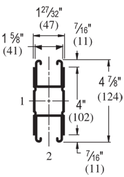
| Elements of Section - P1004A | ||
| Area of Section |
1.965 in2 (12.7 cm2)
|
|
|
Axis 1-1
|
Axis 2-2
|
|
| Moment of Inertia (I) |
4.068 in4 (169.3 cm4)
|
1.092 in4 (45.5 cm4)
|
| Section Modulus (S) |
1.669 in3 (27.4 cm3)
|
1.190 in3 (19.5 cm3)
|
| Radius of Gyration (r) |
1.439 in (3.7 cm )
|
0.745 in (1.9 cm )
|
|
||||||||||||||||||||||||||||||||||||||||||||||||||||||||||||||||||||||||||||||||||||||||||||||
| Beam Loading - P1004A | ||||||
| Span (in) |
Max Allowable Uniform Load (lbs) |
Defl at Uniform load (in) |
Uniform Loading at Deflection |
Lateral Bracing Reduction Factor |
||
| Span /180 (lbs) |
Span /240 (lbs) |
Span /360 (lbs) |
||||
| 24 | *9,100 | 0.01 | *9,100 | *9,100 | *9,100 | 1.00 |
| 36 | *9,100 | 0.05 | *9,100 | *9,100 | *9,100 | 1.00 |
| 48 | 7,000 | 0.08 | 7,000 | 7,000 | 7,000 | 0.94 |
| 60 | 5,600 | 0.13 | 5,600 | 5,600 | 5,600 | 0.89 |
| 72 | 4,660 | 0.19 | 4,660 | 4,660 | 4,660 | 0.83 |
| 84 | 4,000 | 0.26 | 4,000 | 4,000 | 3,630 | 0.78 |
| 96 | 3,500 | 0.34 | 3,500 | 3,500 | 2,780 | 0.72 |
| 108 | 3,110 | 0.43 | 3,110 | 3,110 | 2,200 | 0.67 |
| 120 | 2,800 | 0.52 | 2,800 | 2,670 | 1,780 | 0.62 |
| 144 | 2,330 | 0.75 | 2,330 | 1,850 | 1,230 | 0.52 |
| 168 | 2,000 | 1.03 | 1,810 | 1,360 | 910 | 0.44 |
| 192 | 1,750 | 1.34 | 1,390 | 1,040 | 690 | 0.38 |
| 216 | 1,550 | 1.69 | 1,100 | 820 | 550 | 0.34 |
| 240 | 1,400 | 2.10 | 890 | 670 | 440 | 0.31 |
|
*Load limited by weld shear
|
||||||
Notes:
- Above loads include the weight of the member. This weight must be deducted to arrive at the net allowable load the beam will support.
- Long span beams should be supported so as to prevent rotation and twist.
- Allowable uniformly distributed loads are listed for various simple spans, that is, a beam on two supports. If load is concentrated at the center of the span, multiply load from the table by 0.5 and corresponding deflection by 0.8.
- The lateral bracing factor should be multiplied by the load to determine the load retained based on the distance between lateral braces.
| Part No. | Finish | Length | Weight | Box Qty. |
|
P1004A
|
10
|
668.00
|
10
|
|
|
P1004A
|
20
|
668.00
|
20
|
|
|
P1004A
|
10
|
668.00
|
10
|
|
|
P1004A
|
20
|
668.00
|
20
|
|
|
P1004A
|
10
|
710.20
|
10
|
|
|
P1004A
|
20
|
710.20
|
20
|
|
|
P1004A
|
10
|
668.00
|
10
|
|
|
P1004A
|
20
|
668.00
|
20
|