
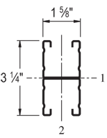
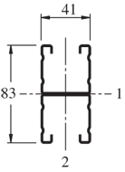

A 1-5/8" x 1-5/8" channel, the Unistrut P2000 is similar in size to the P1001 but with a 16 ga (.060") wall.
| Elements of Section - P2001 | ||
| Area of Section |
0.684 in2 (4.4 cm2)
|
|
|
Axis 1-1
|
Axis 2-2
|
|
| Moment of Inertia (I) |
0.618 in4 (25.7 cm4)
|
0.302 in4 (12.6 cm4)
|
| Section Modulus (S) |
0.381 in3 (6.2 cm3)
|
0.372 in3 (6.1 cm3)
|
| Radius of Gyration (r) |
0.951 in (2.4 cm )
|
0.665 in (1.7 cm )
|
|
||||||||||||||||||||||||||||||||||||||||||||||||||||||||||||||||||||||||||||||||||||||||
| Beam Loading - P2001 | ||||||
| Span (in) |
Max Allowable Uniform Load (lbs) |
Defl at Uniform load (in) |
Uniform Loading at Deflection |
Lateral Bracing Reduction Factor |
||
| Span /180 (lbs) |
Span /240 (lbs) |
Span /360 (lbs) |
||||
| 24 | *1,610 | 0.02 | *1,610 | *1,610 | *1,610 | 1.00 |
| 36 | *1,610 | 0.05 | *1,610 | *1,610 | *1,610 | 1.00 |
| 48 | 1,600 | 0.13 | 1,600 | 1,600 | 1,600 | 0.98 |
| 60 | 1,280 | 0.20 | 1,280 | 1,280 | 1,080 | 0.92 |
| 72 | 1,060 | 0.28 | 1,060 | 1,060 | 750 | 0.85 |
| 84 | 910 | 0.38 | 910 | 830 | 550 | 0.78 |
| 96 | 800 | 0.51 | 800 | 630 | 420 | 0.71 |
| 108 | 710 | 0.64 | 670 | 500 | 330 | 0.64 |
| 120 | 640 | 0.79 | 540 | 410 | 270 | 0.57 |
| 144 | 530 | 1.13 | 380 | 280 | 190 | 0.45 |
| 168 | 460 | 1.56 | 280 | 210 | 140 | 0.38 |
| 192 | 400 | 2.02 | 210 | 160 | 110 | 0.32 |
| 216 | 350 | 2.52 | 170 | 130 | 80 | 0.28 |
| 240 | 320 | 3.16 | 140 | 100 | 70 | 0.25 |
|
*Load limited by weld shear
|
||||||
Notes:
- Above loads include the weight of the member. This weight must be deducted to arrive at the net allowable load the beam will support.
- Long span beams should be supported so as to prevent rotation and twist.
- Allowable uniformly distributed loads are listed for various simple spans, that is, a beam on two supports. If load is concentrated at the center of the span, multiply load from the table by 0.5 and corresponding deflection by 0.8.
- The lateral bracing factor should be multiplied by the load to determine the load retained based on the distance between lateral braces.
| Part No. | Finish | Length | Weight | Box Qty. |
|
P2001
|
20
|
232.00
|
500
|
|
|
P2001
|
10
|
232.00
|
250
|
|
|
P2001
|
10
|
232.00
|
250
|
|
|
P2001
|
20
|
232.00
|
500
|
|
|
P2001
|
10
|
248.00
|
250
|
|
|
P2001
|
20
|
248.00
|
500
|
|
|
P2001
|
10
|
232.00
|
250
|
|
|
P2001
|
20
|
232.00
|
500
|