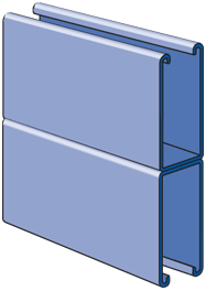
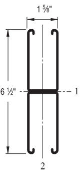
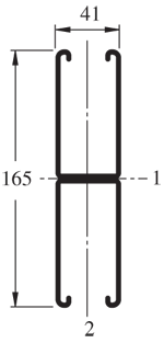
| Elements of Section - P5001 | ||
| Area of Section |
1.793 in2 (11.6 cm2)
|
|
|
Axis 1-1
|
Axis 2-2
|
|
| Moment of Inertia (I) |
6.227 in4 (259.2 cm4)
|
0.866 in4 (36.0 cm4)
|
| Section Modulus (S) |
1.916 in3 (31.4 cm3)
|
1.066 in3 (17.5 cm3)
|
| Radius of Gyration (r) |
1.864 in (4.7 cm )
|
0.695 in (1.8 cm )
|
|
||||||||||||||||||||||||||||||||||||||||||||||||||||||||||||||||||||||||||||||||||||||||||||||
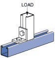
| Beam Loading - P5001 | ||||||
| Span (in) |
Max Allowable Uniform Load (lbs) |
Defl at Uniform load (in) |
Uniform Loading at Deflection |
Lateral Bracing Reduction Factor |
||
| Span /180 (lbs) |
Span /240 (lbs) |
Span /360 (lbs) |
||||
| 24 | *6,890 | 0.01 | *6,890 | *6,890 | *6,890 | 1.00 |
| 36 | *6,890 | 0.02 | *6,890 | *6,890 | *6,890 | 1.00 |
| 48 | *6,890 | 0.05 | *6,890 | *6,890 | *6,890 | 0.97 |
| 60 | 6,420 | 0.10 | 6,420 | 6,420 | 6,420 | 0.90 |
| 72 | 5,350 | 0.14 | 5,350 | 5,350 | 5,350 | 0.83 |
| 84 | 4,590 | 0.19 | 4,590 | 4,590 | 4,590 | 0.76 |
| 96 | 4,020 | 0.25 | 4,020 | 4,020 | 4,020 | 0.68 |
| 108 | 3,570 | 0.32 | 3,570 | 3,570 | 3,360 | 0.61 |
| 120 | 3,210 | 0.39 | 3,210 | 3,210 | 2,720 | 0.54 |
| 144 | 2,680 | 0.57 | 2,680 | 2,680 | 1,890 | 0.43 |
| 168 | 2,290 | 0.77 | 2,290 | 2,080 | 1,390 | 0.35 |
| 192 | 2,010 | 1.01 | 2,010 | 1,590 | 1,060 | 0.30 |
| 216 | 1,780 | 1.27 | 1,680 | 1,260 | 840 | 0.27 |
| 240 | 1,610 | 1.58 | 1,360 | 1,020 | 680 | 0.24 |
|
*Load limited by weld shear
|
||||||
Notes:
- Above loads include the weight of the member. This weight must be deducted to arrive at the net allowable load the beam will support.
- Long span beams should be supported so as to prevent rotation and twist.
- Allowable uniformly distributed loads are listed for various simple spans, that is, a beam on two supports. If load is concentrated at the center of the span, multiply load from the table by 0.5 and corresponding deflection by 0.8.
- The lateral bracing factor should be multiplied by the load to determine the load retained based on the distance between lateral braces.
| Part No. | Finish | Length | Weight | Box Qty. |
|
P5001
|
10
|
610.00
|
100
|
|
|
P5001
|
20
|
610.00
|
200
|
|
|
P5001
|
10
|
610.00
|
100
|
|
|
P5001
|
20
|
610.00
|
200
|
|
|
P5001
|
10
|
646.60
|
100
|
|
|
P5001
|
20
|
646.60
|
200
|
|
|
P5001
|
10
|
610.00
|
100
|
|
|
P5001
|
20
|
610.00
|
200
|